
Wiring
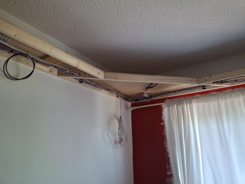
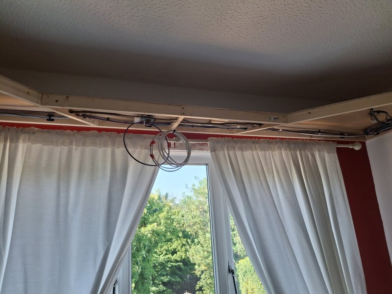
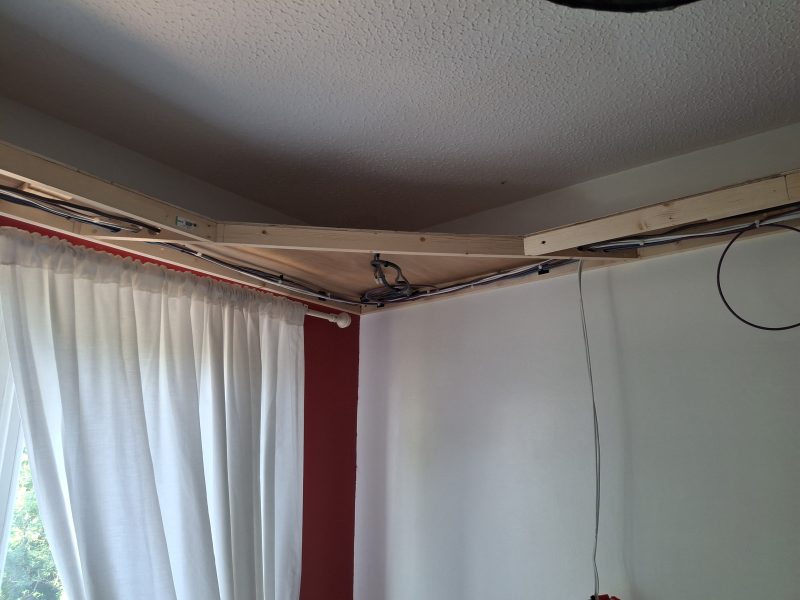
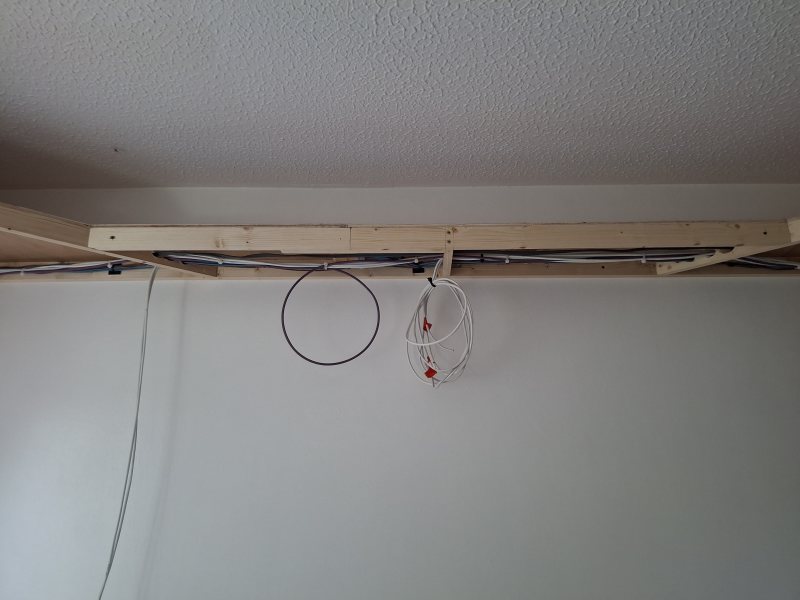
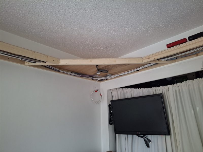
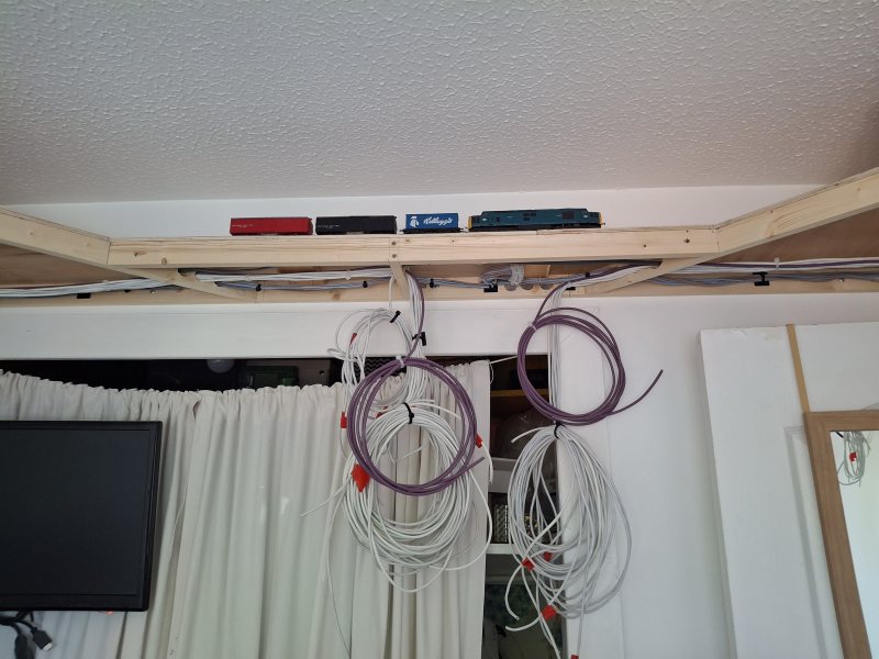
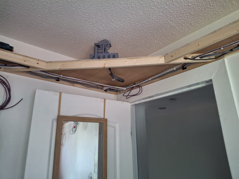
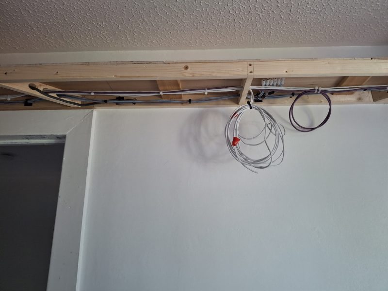
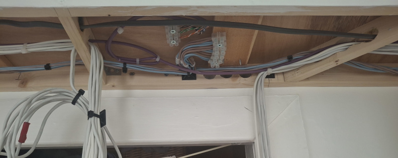
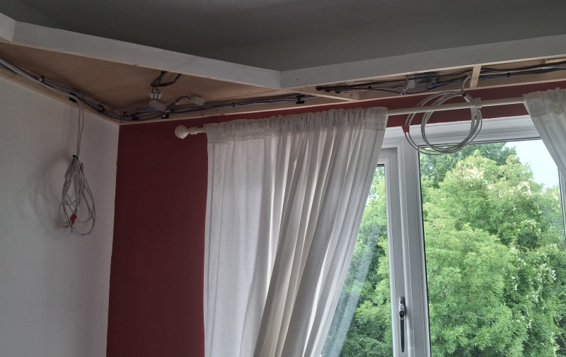
To move the layout on a little, I took the time over a weekend to install the cables through the frame.
The circuits are:
1x 240 volt circuit for frame underside room lighting - to take over from the old spot lights in the ceiling which would now be obscured.
There will be one small LED light in each corner, each with it's own 12 volt power pack.
1x 240 volt circuit passes through for the high level TV socket.
As per BS 7671 (UK wiring regulations) recommendations, the 240 volt circuits are separated from the 12 volt circuits as far as possible.
3x 12 volt track 'bus' circuits - 1.5mm2, wired in a loop to the control position.
One for each track.
1x 12 volt auxiliary power cable - CAT 5 (4 wire pairs), wired in a loop to the control position.
For possible scene lighting application, 2 pairs for day-time lighting, 2 pairs for night-time lighting.
16x 12 volt control, sensing or power wires - 8 core flexible 0.2mm cable.
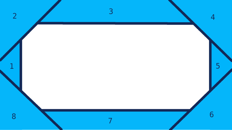
These are wired individually from the control position to each 'section' (four corners, four straights), numbered 1 to 8 clockwise from the control position (in the cupboard).
Baseboard
The following weekend was a bit of a DIY trial, the first task being to get hold of some 9mm plywood.
That proved to be easier said than done, given the sizes required. B&Q advertise their wood cutting service, however the first store had no stock, the second had no cutting service, and the third store's cutting saw was out of order.
So I resorted to buying the panels at the third store, along with a tape measure and a saw, and cut the panels up in the car park until the sheets were able to fit in the car.
That done (with thanks to a few passers-by who helped along the way!) and safely home, I was able to place the sheets individually on the frames and mark them for cutting to their final shape.
Each corner was tackled first: marked, cut then screwed into position, before moving to the next.
The remaining straights were then trimmed to suit and fixed to the frame, and supports were fixed at all of the panel joins.
The screw holes and joins were treated to some filler, and all sanded down.
 |
 |
 |
 |
 |
 |
 |
 |
The cables have been run back to one side of the cupboard, where at a minimum, a 12 volts DC transformer for aux power and a track controller will live.
Following on from this, the baseboard tops and frame fronts were given two coats of matt white emulsion and of course a test track section was placed to see how that looked.
Five minutes of trains moving on this track then somehow happened.
Marking out the track
With the emulsion dried, it was time to mark out the first track locations.
A great discovery was made when I brought the metre rule in from the shed: It is almost exactly the width of Hornby OO track, at 30mm.
Measuring out from the wall 200mm along the straights, I was able to begin to pencil in the track edges for the first loop.
With the first two straights marked out, I had a look at the first 90 degree curve, a Hornby third radius corner.
Measuring out from the wall, and lining the corner up with the straights markings, it seemed that the corner was happiest with the last sleeper of the corner sitting at around 620mm from the wall. This was drawn around and marked up in pencil on the baseboard.
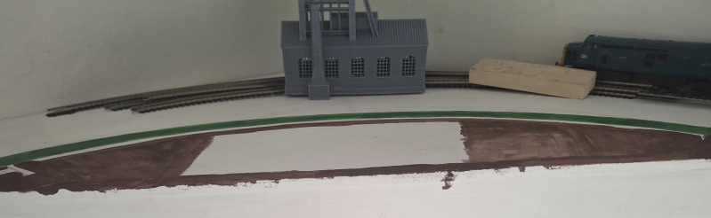
I was then able to do a little colouring-in, painting the track bed in Sap Green coloured acrylic paint and the gap between the track and the front edge of the baseboard in Burnt Umber coloured acrylic paint. The paint is standard craft supplies acrylic, and a little goes a very long way indeed. The acrylic paint will help to seal the plywood from moisture.
I chose a green shade for the track bed because I will be fitting cork over it for the track, but if a little green should peek out, it will be of no real consequence.
Adding the underside covers
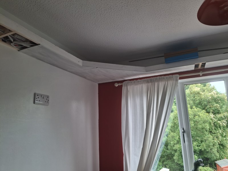
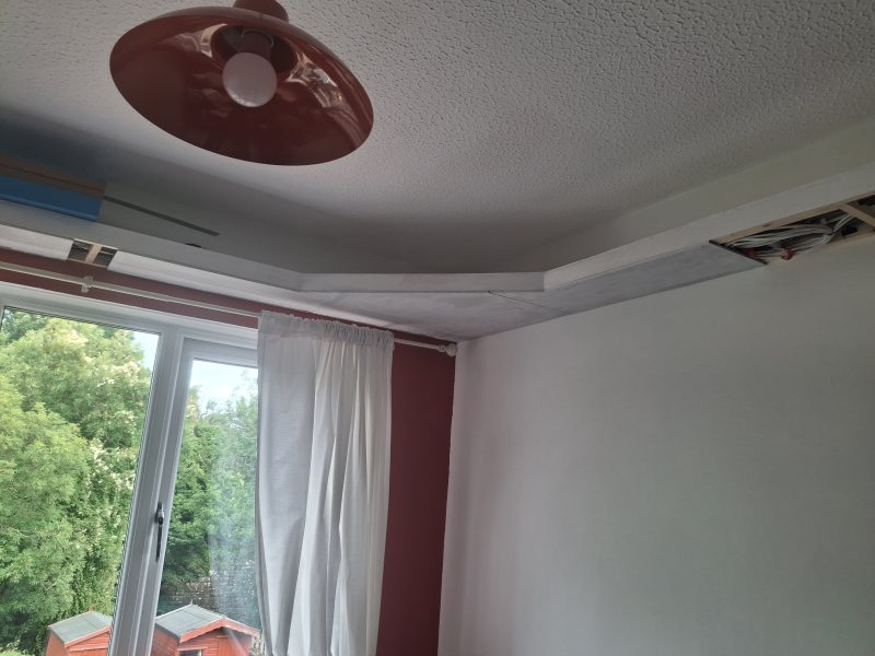
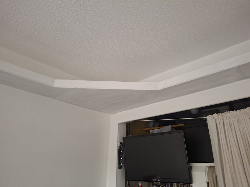
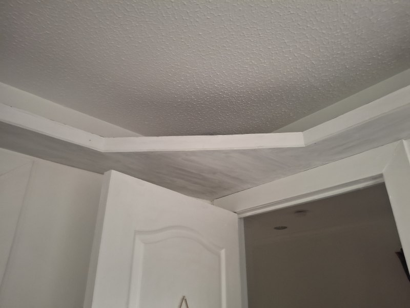
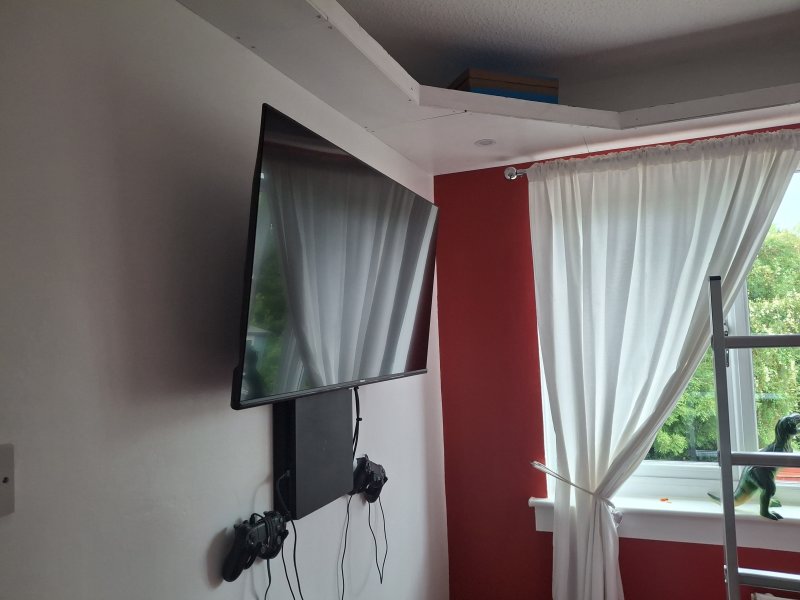
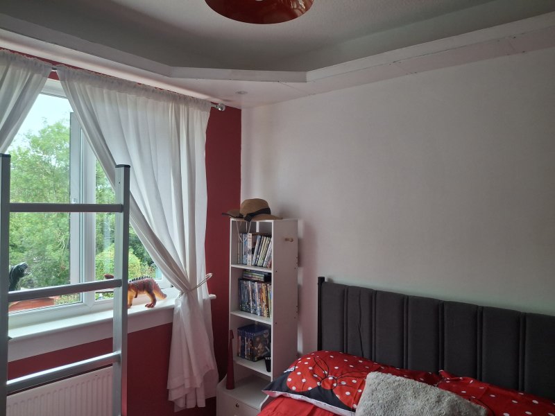
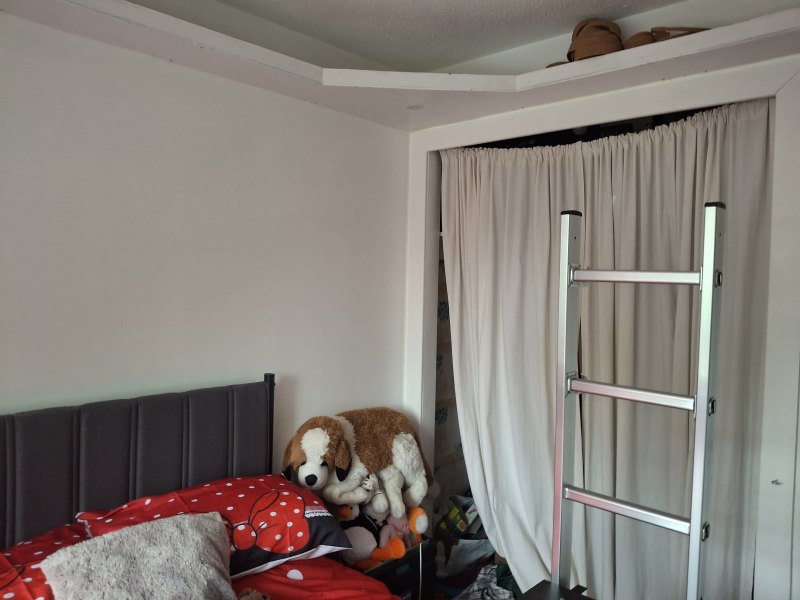
A day has been spent fitting the frame underside covers and priming them. This will allow for fitting of the corner room lights and keeps the cables out the way until they are needed.
 |
 |
 |
 |
The LED lights arrived for the underside corners and were fitted and tested. The underside boards were then removed, treated to two coats of satin eggshell paint, and refitted.
 |
 |
 |
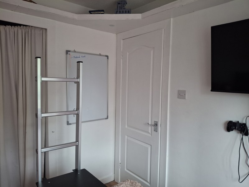 |
With this now fully in place, the front facing can be fitted, and the track marking can continue.