
About Kirdon
Kirdon Electric Limited of Factory Yard, Hanwell, London W7, was founded by George Weston in 1946. He started out with the manufacture of low voltage electrical appliances including solenoids and controllers for model railways, later also producing OO gauge locomotive models. (Reference Kirdon Electric Limited - BinnsRoad.co.uk)
It is thought that Kirdon ceased trading in the late 1950s or 1960s.
The Super Seven
Released by Kirdon around July 1958, the Kirdon Super Seven DC model train controller is now a relatively rare, three output 12 volt DC variable speed controller with 16 volt AC (for Solonoids [sic]) and 4 volt AC (for lighting) auxiliary outputs.
There were several Kirdon train controller stablemates, such as the Senior (two output, 3 amp), the DC/5 (single output, 5 amp), The Minor (two output, 1 amp) and the DC/1 Junior (single output, 2 amp)
I have not yet been able to pin down a manufacture date or specification for this Super Seven, and it is the only three output Kirdon model I have found so far.
There are no manufacturers labels or marks inside or on the case, other than the printed face plate.
An exterior clean
The unit had accumulated quite some storage grime, and so a gentle going over the outside with a toothbrush in warm water took at least some of the dust off.
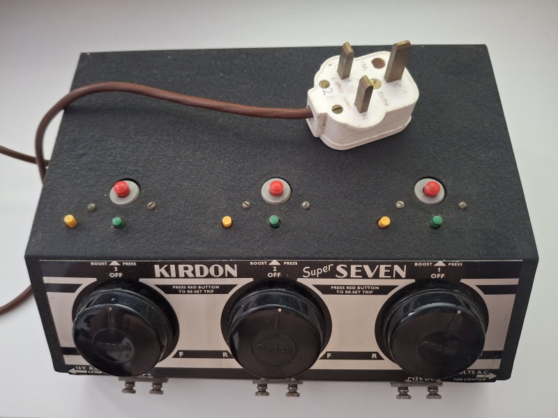
A first look over (the outside)
The controller was supplied with an un-sleeved (original style) 13 amp plug, fitted with a 2 amp fuse (probably not original).
The brown mains flex to the unit is the original Red/Black/Green (pre-1970s) and is very thin.
The dials have a screw fixing onto a post.
Terminals are dirty, with light corrosion.
The unit powers up without fuss, one output is reliably supplying 12 volts DC (the left one).
Looking inside
The dials were removed and light corrosion was found.
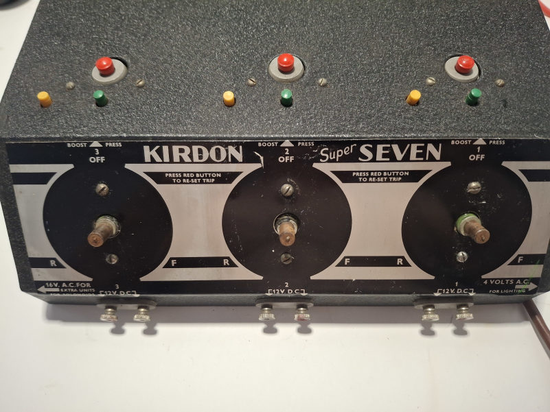 |
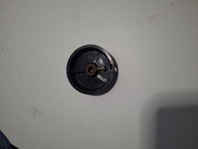 |
Opening the unit up for a visual inspection, a few items need attention, one of which I will need to look into a bit more before moving forward.
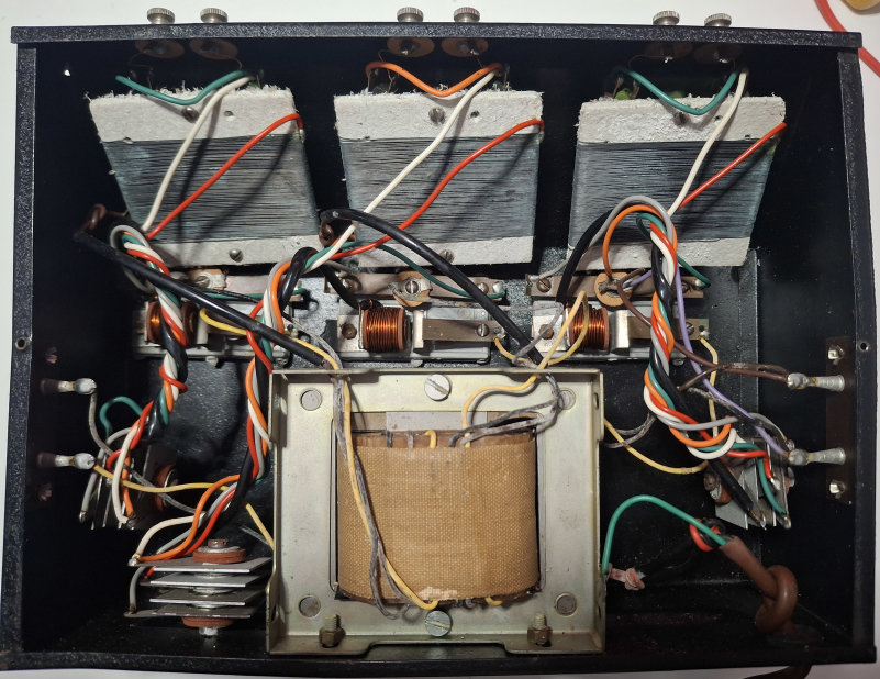
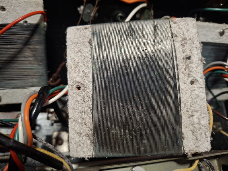
The variable resistor coils (top of the picture above) are wound onto what looks very much like square sheets of asbestos. This would make historic sense, as the asbestos could withstand any heating of the coils, but they pose a hazard in and of themselves. The windings are also lightly corroded and dirty (see pic. below.)
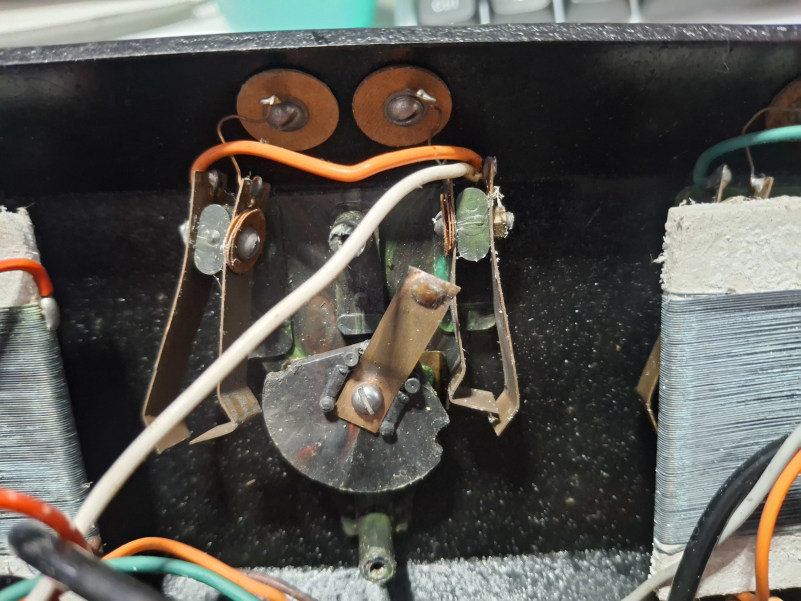
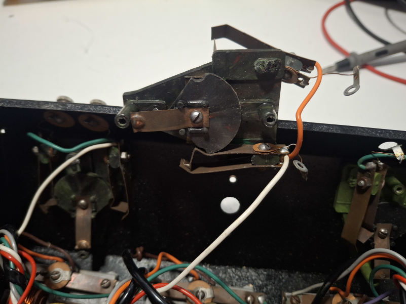
The control knob actuates two sets of switches for forward and reverse - one of the switch sets have broken off on two of the outputs, as the plastic mounting plate has become brittle with age.
A solution to this needs to be found.
 |
 |
The flex is soldered directly onto the transformer primary without any intermediate fusing and a knot in the flex suffices for a strain relief.
All of the internal contacts are dirty.
So what needs done?
Look into replacing or encapsulating the asbestos.
Repair or replace the broken switches on the middle and right hand output dials.
Replace the ancient flex and plug.
Provide in box fusing of the mains feed to the primary coil of the transformer.
The circuit
Working through the internal circuit, we find the following:
The mains transformer has four sets of secondary windings, one set solely provides the 16 volts AC to the 'Solonoids' output.
The windings for the RH dial also feed out to the 4 volts AC output.
The windings for the LH and Middle dials only deal with themselves.
There is an overload coil in line with the +16 volts AC winding for each dial
When the dial is in the centre position, the DC output circuit is open.
With the dial in full forward or reverse, output voltage is 15.9 volts DC no load)
When the Yellow button is pressed, voltage drops to 8 volts DC.
When the Green button is pressed, voltage increases to 19.9 volts DC
AC output voltages
16 volts AC (19.51 volts no load)
4 volts AC (5.57 volts no load)
[currently working on the circuit diagram]
Collecting parts
June 26 - Purchased a switched and fused IEC (kettle style) socket via Ebay - £2.90 (Just arrived from China.)
I have got hold of a small amount of PEI Polyethermide sheet and will be making replacement switch posts from this.
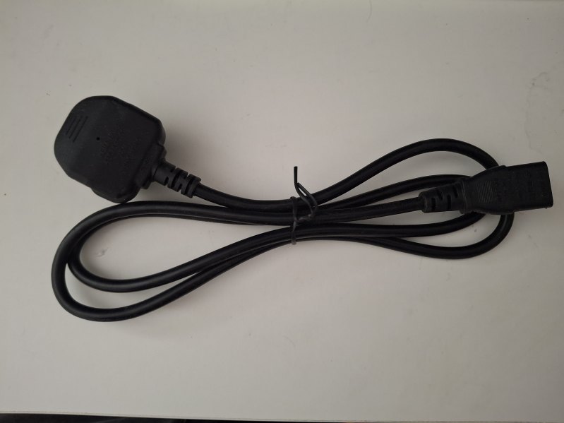
I have located an IEC lead with a UK plug.
Starting repairs
Repair list:
1) Fit IEC socket and replace flex with IEC lead.
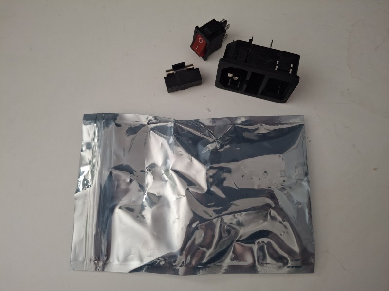
The IEC socket arrived from China, and the controller box was measured for a fitting location. I looked out an IEC power lead to match.
 |
 |
The socket comes with a fuse and a mains switch.
The socket was marked out on the box, drilled and cut out and the hole edges filed up to the correct fit.
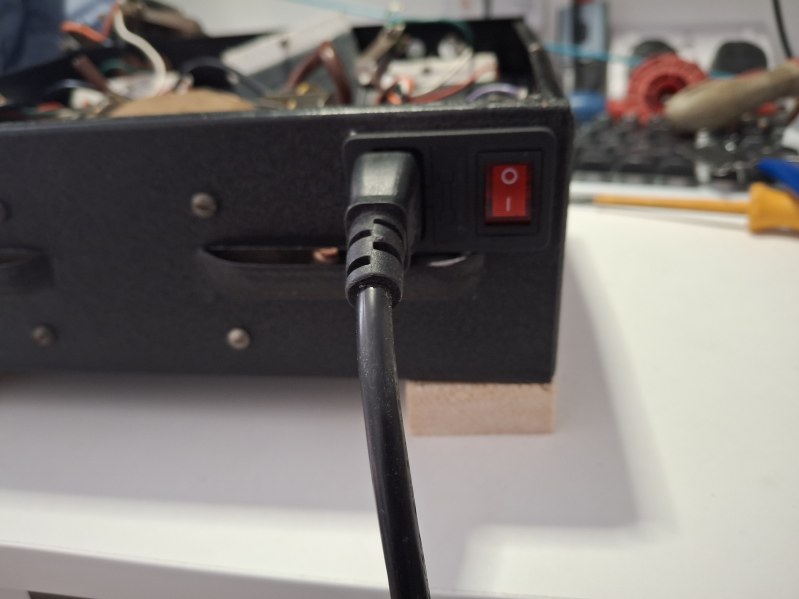
The terminals were then wired and soldered as required.
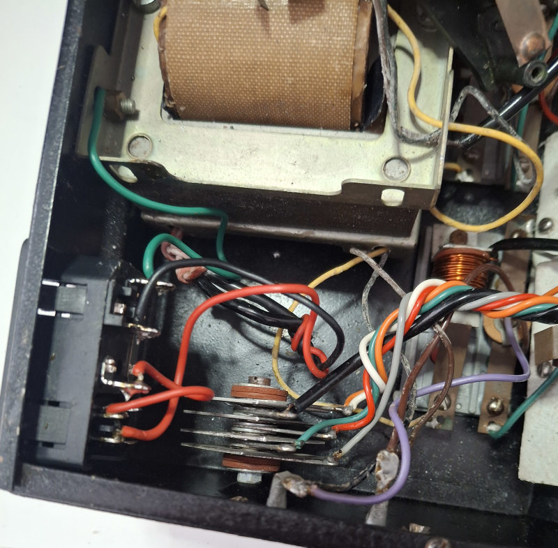
With this tested, it was time to look at the switching issues.
2) Resolve switching
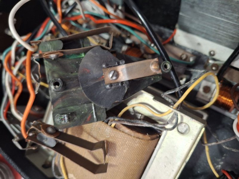
Two of the three channels have broken switching posts, due to the plastic going brittle with age.
August Update:
I bought a 'spares' Kirdon controller which, it turns out, has exactly the same problems as the original only worse.
I have now started to repair one switch bracket with a view to taking moulds from it to make new ones. I have modelled new, larger switch posts and have almost readied the bracket for moulding.
I have made a rudimentary mould box.
September update:
I have prepared the switch bracket for moulding and poured the first half of the mould.
Mixed results so far.
Testing
Costs
Controller purchase price from Ebay: £15 plus P&P.
Parts:
IEC Socket £2.90 inc. P&P
IEC lead (free)
PEI Polyethermide sheet (free)
Spares controller purchase from Ebay: £21.25 plus P&P.
Future