This circuit can be configured to allow automatic train journeys on a open ended track configuration, travelling 'end-to-end' safely without manual control being required.
This circuit assumes DC loco operation only (Not suitable for DCC).
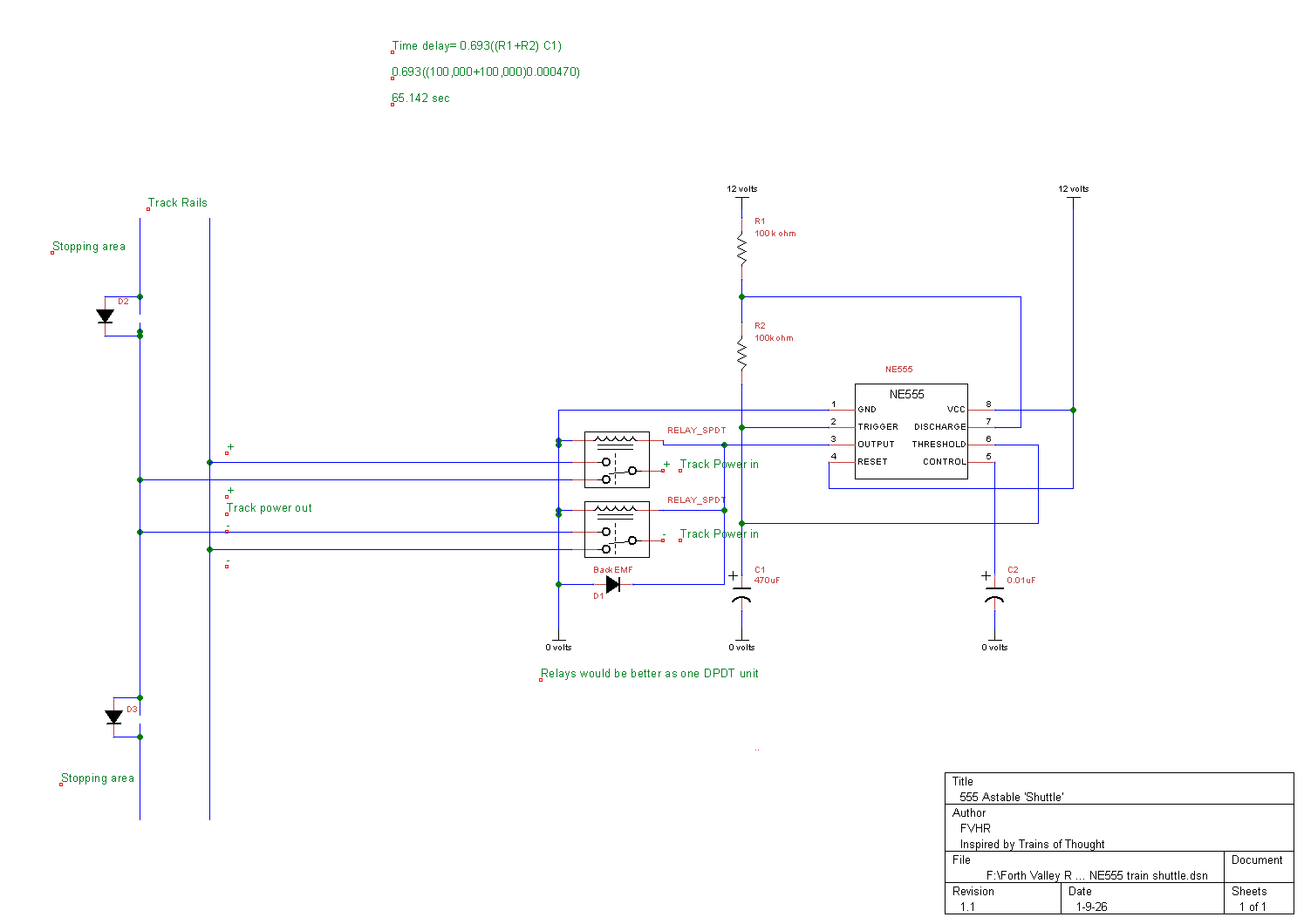
This circuit, using the NE 555 chip at its core, is configured as an astable multivibrator.
The voltage divider and charging current resistors, R1 and R2, limit charging current to capacitor C1, and the discharge current through the chip. The values of these components also determines the timing for the output state of chip Pin 3.
Chip pins
Pin 1 (Ground) is connected to supply 0 volts.
Pins 2 (Trigger) and 6 (Threshold) connect between resistor R2 and capacitor C1.
Pin 3 (Output) supplies the relay coil control voltage.
Pins 4 (Reset) and 8 (Vcc) are tied to supply +12 volts.
Pin 5 (Control) is connected to capacitor C2, which is connected to 0 volts.
Pin 7 (discharge) on the chip controls state change, when the input voltage reaches roughly 2/3rds of the supply voltage - in our case around 8 volts of the 12 volts supplied to the circuit.
Timing
In the diagram above, R1 and R2 values are 100 kilo ohms and C1 value is 470 micro farads.
Following the equation:
Time Delay (seconds) = 0.693((R1+R2)C1)
=0.693x((200,000)x0.000470)
=0.693x94
=65.1 seconds
Thus, running this circuit with the listed values, Pin 3 will be 'ON' for around 65 seconds and 'OFF' for 65 seconds.
The control relay
The control relay switches track power to the required polarity, determined by the output state of chip Pin 3. The track power is supplied by a suitable DC track controller, set to the appropriate setting.
The relay switch connections can be oriented in such a way that only one pair of droppers is required to the centre of the track run, we will prepare another drawing to cover this configuration.
Circuit operation
If we assume that the track is long enough for the loco to move at a pre-determined speed for the configured 65 seconds without incident, when the state of Pin 3 changed the loco would immediately reverse and run in the opposite direction for a similar time, and so on.
Of course trains don't often change direction without stopping, so we need to ensure that the timing allows the train to reach the end of the track, build in 'stopping areas' and ensure that these areas are configured to ensure that the loco pickups will only operate the loco motor to return back along the track once the control relay has changed over. This is achieved by cutting one rail at the beginning of the stopping area, and bridging the gap with a diode, thus allowing electricity to flow only in one direction. The stopping area will most likely be slightly longer than the loco at one end, and slightly longer than the train at the other (to prevent crashes). The cuts and diodes must be on the same rail at each stopping area of the track.
When the loco pickups cross over the diode gap at the stopping area, the electricity is removed and the train stops, waiting for the track power to change polarity, which allows the train to energise and move off in the opposite direction, where eventually it will cross over the diode gap at the opposite end. Again the electricity is removed and the train stops, waiting for the track power to change polarity once more. For this reason the orientation of the diodes are paramount to correct operation of the circuit, and both must be oriented in the same direction.
Thus, a rudimentary train shuttle circuit can be achieved. Placing stations or facilities at each end of the line, or placing a scenic break, such as a tunnel at one end and a station at the other can give purpose to the shuttle configuration.
Parts
Resistors, all 1/3 watt 5%.
R1 and R2 - 100 kilo Ohm.
C1 470 micro farad electrolytic 25 volt.
C2 0.01 micro farad electrolytic 25 volt.
D1, D2 and D3 - 1N4001.
NE555 chip, socket optional.
1x 12 volt DC DPDT subminiature relay (or 2x. 12 volt DC SPDT subminiature relays as shown above).
12 volt DC power supply.
DC track controller.