
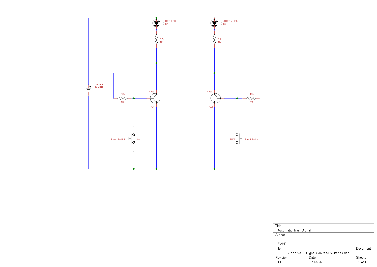
This circuit controls a two colour (red and green) signal, and automatically switches from green to red as the signal is passed by a train. It is automatically reset to green again when the train has progressed along the track to some pre-determined detection point.
Of course the circuit has to be able to detect when the train is passing the signal, and must also be able to detect when the train is passing the position on the layout where the signal should be reset to green. In this circuit we are using a pair of reed switches which will be operated by a small magnet fitted to the train.
A 'normally open' reed switch can be closed by placing a magnet close to it. The presence of the magnet causes the switch to become slightly magnetised, and the two ends that are nearly touching have opposite poles so that they are attracted to one another and the switch is closed. When the magnet is moved away, the switch opens once again.
In this situation the reed switches are placed on or under the track at the places where it is desired that the train should set and reset the signal. It is possible to fit the reed switches under the track, or between two sleepers, although it may be necessary to file the plastic web between the sleepers away slightly in order to make sufficient space for the reed switches. It is also possible to fit the reed switches lengthwise down the centre or to one side of the track, although this location will be more noticeable without camouflage. In either case it is necessary and desirable to use the smallest possible reed switches.
Although the electric motors used in model trains contain permanent magnets, these cannot necessarily be relied upon to operate the reed switches, although in a few cases it may be found that they do so and no additional magnet is required. Magnets to operate reed switches are readily available and it is not difficult to fit one of these to the underside of the train. It may be possible to simply glue on the underside of the train at some point, or it may be necessary to open up either the locomotive or part of the rolling-stock so that the magnet can be fitted on the inside on the base panel. This depends upon the amount of clearance beneath the train, and how well the magnet can be concealed if it is fitted on the exterior of the train.
For maximum reliability the magnets and reed switches should be on the same alignment. Therefore if the reed switches are fitted across the track, the magnet should be fitted across the train. If the reed switches are fitted lengthwise on the track, the magnet should be mounted lengthwise on the train.
The Circuit
The circuit is based on a bistable multivibrator, the circuit diagram is shown above.
The circuit is fed from a 12 volts DC supply. When power is initially connected to the circuit the two transistors will begin to switch on, but once it has fully powered up one transistor will be 'on', and the other 'off'. Here we will assume that once fully powered up, the GREEN LED is lit (this may not always be the case).
If a train passes over and briefly operates reed switch SW2, Q2's gate terminal will be briefly taken to the negative supply potential and Q2 will consequently be switched to 'off'. This causes its drain to rise to virtually the full supply potential, causing Q2 to switch to 'on', which illuminates the RED LED D1.
If reed switch SW1 is now operated by the train, Q1 is switched to 'off', and the circuit reverts to its original state, and the GREEN LED D2 is illuminated.
In this way simple single direction signalling can be achieved.
The location of the reed switches are key to circuit operation, however the circuit itself is very small, and most of it is either on the track (reed switches) or beside it (LED signals), with only the components needing to be located elsewhere.
A normally open push switch can be fitted in parallel with the reed switch to test the circuit manually without running trains (by-passing the reed switch), or to reset the signals if required.
Parts
Resistors, all 1/3 watt 5%.
R1 and R2 - 1k Ohm.
R3 and R4 - 10k Ohm.
2mm RED LED.
2mm GREEN LED.
(Choose LEDs that best suit your application. R1 and R2 values may need to change to balance the light levels from each LED.)
Q1 and Q2 - NPN transistor VN66AF or equivalent.
'Normally open' miniature reed switches.
Optional 'Normally open' push (momentary) switches.